Tested to VDI 6022

Tested to VDI 6022
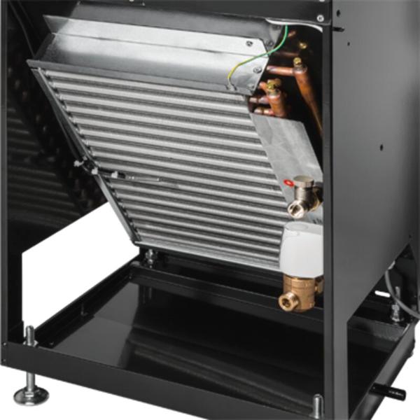
Water connections
Filter change
Levelling foot
Functional description
Decentralised supply and extract air units ventilate the room and cover the cooling and heating load in accordance with the technical data. An EC centrifugal fan takes in the outdoor air which then flows through the motorised shut-off damper and the outdoor air filter.
The outdoor air then flows through the cross flow heat recovery unit, which can be switched off if it is more energy efficient. If necessary, the air is heated by the heat exchanger before it is discharged to the room as a displacement flow.
The extract air first passes through the extract air filter, then flows through the heat recovery unit, the extract air fan and the motorised shut-off damper before it is discharged to the outside as exhaust air.
If the indoor air quality is sufficient, the FSL-CONTROL III control system switches to energy-efficient secondary air mode by closing the outdoor air dampers. The control system compares the room air quality setpoint value to the actual value measured by the CO2 sensor and switches automatically between outdoor air and secondary air operation.
In case of a power failure, the outdoor air and exhaust air dampers are closed to ensure fire protection, frost protection and to avoid draughts. This is ensured by a capacitor in each actuator.
Near the external wall, the supply air is discharged into the room with a medium velocity between 0.5 and 0.8 m/s. Due to the induction effect, the supply air velocity is rapidly reduced after entering the room. As a result, in cooling mode, the supply air spreads out like displacement flow over the entire floor area. Near heat sources such as people or equipment, a lift current is formed by natural convection, so that the air is exchanged primarily in these areas.
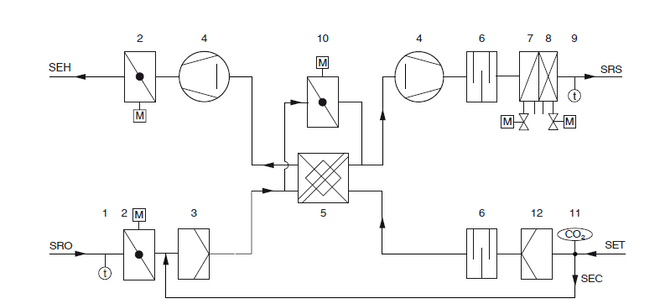
1 Outdoor air temperature sensor (optional)
2 Shut-off damper with actuator (exhaust air and outdoor air)
3 Outdoor air filter ISO ePM1
4 Fan (supply air and extract air)
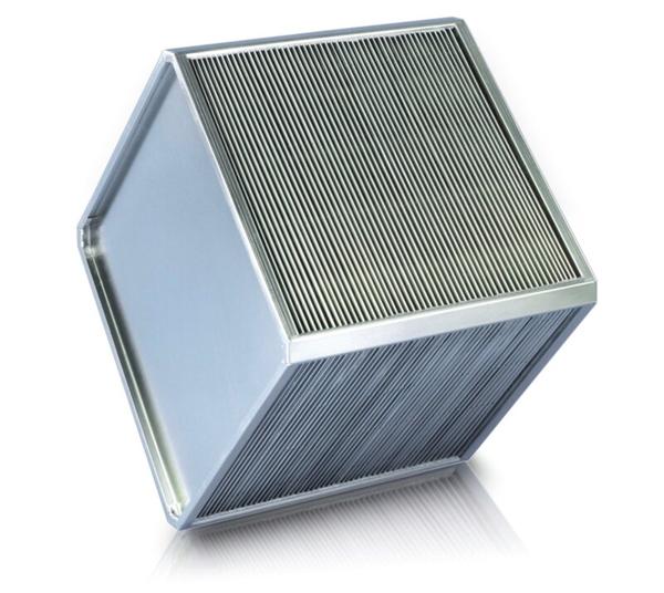
5 Recuperative cross flow plate heat exchanger
6 Sound attenuator
7 Heating coil
8 Cooling coil (only SCHOOLAIR-V-4)
9 Supply air temperature sensor
10 Bypass damper with actuator
11 CO2 sensor (optional)
12 Extract air filter ISO coarse
SEH Single room exhaust air
SET Single room extract air
SRO Single room outdoor air
SRS Single room supply air
SEC Secondary air (optional)
Functional description
Decentralised supply and extract air units ventilate the room and cover the cooling and heating loads in accordance with the technical data. An EC centrifugal fan draws in the outdoor air, which flows through the motorised shut-off damper and the outdoor air filter. The outdoor air then passes through the crossflow heat recovery unit, which can be switched off under operating conditions where heat recovery is not required. If required, the air is heated by the heat exchanger before being discharged into the room as a displacement flow. The extract air passes through the extract air filter, before being discharged to the outside as exhaust air, via the cross-flow heat recovery unit, the extract air fan and the motorised shut-off damper. If the indoor air quality is adequate, the FSL-CONTROL III control system switches to energy-efficient secondary air mode by closing the outdoor air dampers. The control system compares the room air quality setpoints to the actual values measured by the CO2 sensor and switches automatically between outdoor air and secondary air operation. In case of a power failure, the outdoor air and exhaust air dampers are closed to ensure fire protection, frost protection, and to avoid draughts. This function is ensured by a capacitor in each actuator. The supply air flows into the room close to the façade at an average velocity of 0.5 – 0.8 m/s. As a result of the induction effect, the air velocity is rapidly reduced shortly after the air enters the room. As a result, in cooling mode the supply air spreads across the entire floor area as displacement flow. At heat sources such as people or equipment, natural convection creates a buoyant airflow, so that air exchange primarily occurs in these areas.
Width | 397 mm |
Height | 2160 mm |
Depth | 359 mm |
Volume flow rate | 150, 200, 250 m³/h (boost 320 m³/h) |
nominal volume flow rate | 250 m³/h |
Sound power level | 31 – 46 dB(A) |
Heat recovery efficiency | 52 % |
Maximum operating pressure, water side | 6 bar |
Maximum operating temperature | 75 °C |
Supply voltage | 1~ 230 V AC, ±10 %, 50/60 Hz |
Power rating | 226 VA |
Weight | 70 kg |
This specification text describes the general characteristics of the product. Texts for variants can be generated with our Easy Product Finder design programme.
Specification textKO
KM
SL
Control function Slave
With Modbus TCP
Modbus TCP interface (Ethernet):
BI
With BACnet IP
BACnet IP interface (Ethernet):
MR
Only with control function MA
With Modbus RTU
Modbus RTU interface (RS 485):
BM
Only with control function MA
With BACnet MS/TP
BACnet MS/TP interface (RS485):
C
Only with control function MA
Air quality sensor
With CO2sensor:
V
Only with control function MA
Air quality sensor
With VOC sensor
A
With outside air temperature sensor (only with MA control function)
HV
Thermoelectric valve actuator:
HVE
Electromotive valve actuator
R
Lockshield
0.25
Straight-through small valve:
0.63
Straight-through small valve:
1.00
Straight-through small valve:
F0.50
Pressure-independent control valve
Replacement filter set
| SA-V | – | – | 2 | – | 1 | – | KO | / | 397 × 2160 × 359 | / | C3 | – | MA | – | T | / | MR | / | C | / | Z | / | A | / | HV | – | R | – | 0,40 | |
| | | | | | | | | | | | | | | | | | | | | | | | | | | | | | | | | |||||||||||||||
| 1 | 2 | 3 | 4 | 5 | 6 | 7 | 8 | 9 | 10 | 11 | 12 | 13 | 14 | 15 | 16 |
1 Type
SA-V vertical decentralised ventilation unit X-CUBE/SCHOOLAIR-V
2 Variant
No entry: Standard
3 Heat exchanger
2 2-pipe
4 Heat exchanger construction
Specify construction (technical design with TROX EPF or TROX CONFIGURATOR)
5 Construction
KO without condensate drain
KM with condensate drain
6 Nominal size [mm]
Width x height x depth
397 x 2160 x 359
7 Control system
OR without control system
C3 with FSL-CONTROL III
8 Control function
MA Master
SL Slave
9 Real-time clock
Only with control function MA
No entry: without real time clock
T with real time clock
10 Interface
No entry: without interface
MT with Modbus TCP
MR with Modbus RTU (only with control function MA)
BI with BACnet IP
BM with BACnet MS/TP (only with control function MA)
11 Air quality sensor
Only with control function MA
No entry: without air quality sensor
C with CO2 sensor
V with VOC sensor
12 Supply air temperature sensor
Z with supply air temperature sensor
13 Outdoor air temperature sensor
Only with control function MA
No entry: without outdoor air temperature sensor
A with outdoor air temperature sensor
14 Heating valve
HV with thermoelectric actuator
HVE with electromotive actuator
15 Lockshield – heating circuit
R with lockshield
16 Kvs value heating valve
0.25 (straight-way valve)
0.40 (straight-way valve)
0.63 (straight-way valve)
1.00 (straight-way valve)
F0.50 (pressure-independent control valve)
Order example: SA-V-2-1-KO/397x2160x359/C3-MA-T/MR/C/Z/A/HV-R-0.40
| Type | SA-V | Ventilation unit for ceiling installation X-CUBE/SCHOOLAIR-V |
| Variant | - | Standard |
| Heat exchanger | 2 | 2-pipe |
| Heat exchanger construction | 1 | Heat exchanger type 1 |
| Construction | KO | without condensate drain |
| Nominal size [mm] | 397×2160×359 | Width 397, height 2160, depth 359 |
| Control system | C3 | with FSL-CONTROL III |
| Control function | MA | Master |
| Real time clock | T | with real time clock |
| Interface | MR | with Modbus RTU |
| Air quality sensor | C | with CO2 sensor |
| Supply air temperature sensor | Z | with supply air temperature sensor |
| Outdoor air temperature sensor | A | with outdoor air temperature sensor |
| Heating valve | HV | with thermoelectric actuator |
| Lockshield heating circuit | R | with lockshield |
| Kvs value heating valve | 0.40 | 0.40 (straight-way valve) |
Partager la page
Recommander cette page
Recommander cette page en envoyant un lien par mail.
Partager la page
Merci pour votre recommandation !
Votre recommandation a été envoyée et devrait arriver dans les plus brefs délais.
Contact
Nous sommes à votre disposition

Veuillez préciser votre message et le type de demande
Tel.: +32 (0) 2/522 07 80
Contact
Merci pour votre message !
Votre message a été envoyé et sera traité dans les plus brefs délais.
Notre département de traitement des demandes prendra contact avec vous dès que possible.
Pour les questions d'ordre général concernant les produits ou services, vous pouvez aussi nous appeler :
Tel.: +32 (0) 2/522 07 80
Contact
Nous sommes à votre disposition
Veuillez préciser votre message et le type de demande
Tel.: +32 (0) 2/522 07 80
Contact
Merci pour votre message !
Votre message a été envoyé et sera traité dans les plus brefs délais.
Notre département de traitement des demandes prendra contact avec vous dès que possible.
Pour les questions d'ordre général concernant les produits ou services, vous pouvez aussi nous appeler :
Tel.: +32 (0) 2/522 07 80